In a circular clarifier it could be up to 10. Weir length ft π x 100 ft.
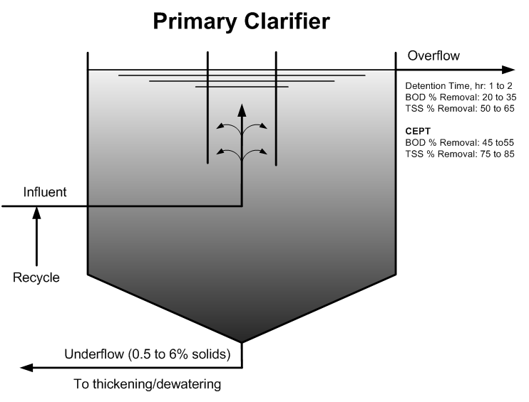
Wastewater Clarifier Performance
Qo primary effluent flow rate in MGD US or m3d SI A total surface area for secondary clarifiers in ft2 US or m2SI Qr recycle activated sludge flow rate in MGD US or m3d SI.
. A Akinola 1 circular Clarifier tanks shows that the Existing such as operations cost cost of drives and Clarification unit of City of Springfield WWTP constructioninstallation cost must be considered to will cost US2217609ton of carbon steel while make a decision on the number of tanks the computer design model with 3 circular SWWTP Ohio USA City of Springfield. The activated sludge system has MLSS concentration of 4160 mgl. If a unique clarifier is proposed the design engineer shall submit operational and design data justifying its use.
Area ft 2 0785Diameter 2. Area ft 2 176625 ft 2. Circular Clarifier Design Calculation.
The expected range of weir overflow rate. Calculate minimum required surface area and clarifier diameter 3. PDF On Jan 1 2009 Nikolay Stojanov Voutchkov published Clarifier Design Find read and cite all the research you need on ResearchGate.
A circular clarifier has a diameter of 150 ft. In a circular center-feed clarifier the inlet baffle should have a diameter of 15 to 20 percent of the clarifier diameter and should not extend more than 3 feet below the water. Clarifier Loading Calculations Tank Volume MG X 24 Flow into Tank MGD Detention Time DT Flow gallonsday Surface Overflow Rate SOR Surface Area ft2 Weir Overflow Rate WOR Flow gallonsday Length of Weir ft Solids Loading Solids lbsday Surface Area ft2.
Calculate acceptable surface overflow rates 2. The water flow is evenly distributed and spirals down around the annulus of the clarifier by means of a. With the center feed well the effluent is discharged along the outer wall of the clarifier tank.
One 1 prefabricated center feed circular mechanical clarifier complete and ready for operation in accordance with the plans and specifications stated herein. Circular clarifier design calculation Valentines Working day is approaching it is just per month absent but There are tons of stuff to prepare from attire into the ingesting put from bouquets to your gifts baskets Weve got to arrange anything for our family members. Clarification is the separation ofsolids from the liquid stream to produce a clarified efflu-ent with low effluent suspended solids ESS.
For a circular thickener with a 1524 m 50 f t dia. The clarifier shall be a Model CMC-_____ prefabricated steel package as. Calculate the Detention Time in HOURS for a clarifier with a volume of 25000 gallons that receives a flow of 310000 galday.
Circular Clarifiers normally utilize a center feed inlet well or a peripheral inlet. Circular clarifiers shall be provided with symmetrical baffling a minimum of 6 inches inside the weir plate to distribute the flow uniformly in all radial directions. Detention Time Volume Flow 25000 gallons 310000 gallonsday 008 Days 008 Days X.
Circular clarifier design preferred by engineers and plant operators for municipal and indus-trial applications. If the diameter of the weir is 100 ft what is the weir loading rate in gpmft. A circular clarifier receives a flow of 425 MGD.
Functions of a Clarifier The final clarifier must perform two pri-mary functionsclarification and thickening. 512 Number of Units Multiple units capable of independent operation shall be provided in all facilities where design flows exceed 250000 gallons per day. The center feed well design can be equipped with a chemical addition system with mixing and flocculation.
In circular clarifiers the radiusheight is usually between 25 and 8. Q primary effluent flow m3h A Settling horizontal surface decantation total projected surface m2 Global hydraulic loading rateIs obtained by dividing the outflow from the horizontal area occupied by. The decanter not including projections tubes or lamellae.
If the flow to the unit is 485 MGD what is the surface loading rate in gpdft 2. 485 MGD x 1000000 gal1MG 4850000 gpd. Weir length ft π x Diameter.
Applied flux G f x f Q f A 8a 8b Applications to thickener design Once the settling flux curve is drawn the optimum operating point can be determined. The expected range of surface loadingsettling rate for a primary clarifier is 300 to 1200 gpdsq ft ballpark estimate. Calculations are carried out and presented for comparison with experimental measurements of point velocities in a shallow circular clarifier in operation at a UK waste water treatment works.
The expected range of. Next convert MGD flow to gpd. Calculate the weir overflow rate.
In rectangular clarifiers lengthwidth ratio is between 15 and 75 usually 3. 22 feet Length of Weir ft X Weir Diameter 314 X 22 ft 6908 ft WOR galdft Flow gallonsday Length of Weir ft Clarifier Loading Hydraulic Loading - Weir Overflow Rate WOR Example 1. Secondary Clarifier Design Fourche Creek WWTP 10 PurposeObjective Perform calculations necessary to design the new circular secondary clarifier for the Fourche Creek WWTP in Little Rock AR.
A Pi r 2 1824 m 2 7 The applied solids feed rate can now be calculated as a flux - see Eqs. Designalthough Types IIIand IV settling may also occur to a limited extent. Area ft 2 0785150 ft 2.
To determine the feet of weir use the formula. Remember to find the area of a circle use. Hydraulic detention time for a primary clarifier is 1 to 3 hours.
Circular peripheral flow wastewater clarifiers The circular peripheral flow clarifier offered by PCS operates with the water flow entering the system at the periphery. The slope of the floor of a rectangular clarifier is usually 1. The flow to a circular clarifier is 690000 gallons per day.
Size Energy Dissipating Inlet 4. We will evaluate existing clarifiers and recommend improvements to influent and effluent geometry feedwellEDI design weir and launder geometry skimming and scum baffles sludge removal systems. Typical Design Value 2 3 Hours 17.
SOR QoA SLR Qo QrXA and WOR QoL where. Otherwise the number of. Return activated sludge recycle ratio is 1.
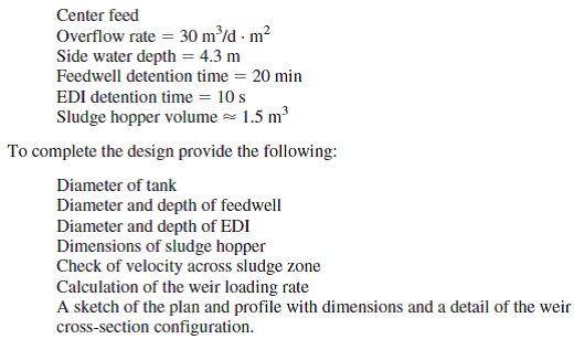
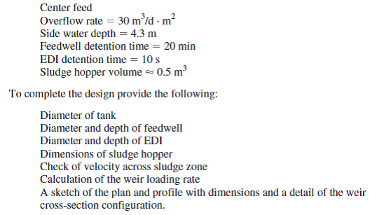
Design circular secondary clarifiers for an extended aeration activated sludge system receiving a flow of 250 000 m3d average 375 000 m3d peak flow.
Solved Design A Circular Clarifier For A Flow Rate Of 34 560 M3 D Chegg Com
Solved Design A Circular Clarifier For A Flow Rate Of 8 450 M3 D Chegg Com

Diseno De Clarificadores
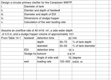
Design A Circular Primary Clarifier For The Camptown Chegg Com
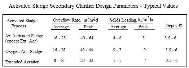
Activated Sludge Secondary Clarifier Design Spreadsheetlow Cost Easy To Use Spreadsheets For Engineering Calculations Available At Engineering Excel Spreadsheets

Wastewater Clarifier Performance
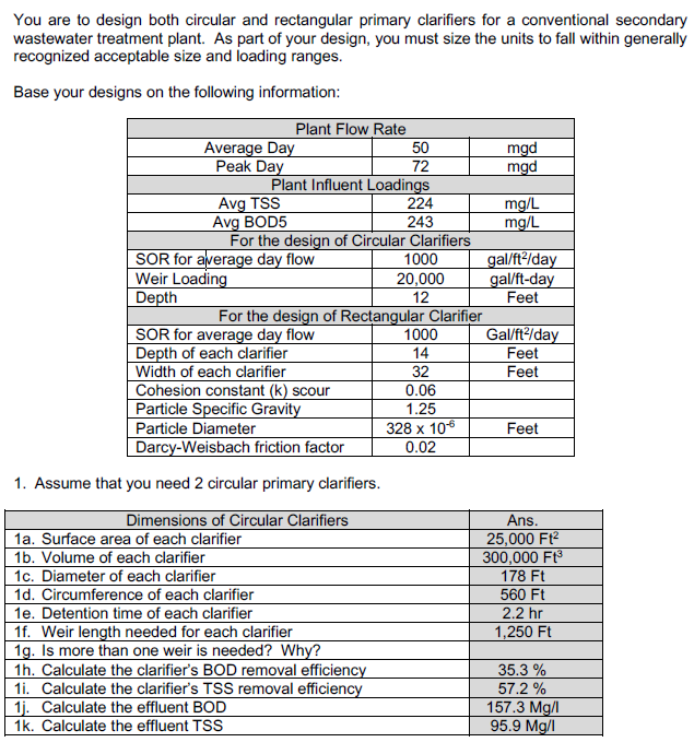
Solved You Are To Design Both Circular And Rectangular Chegg Com
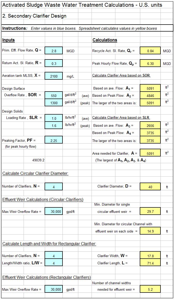
Activated Sludge Secondary Clarifier Design Spreadsheetlow Cost Easy To Use Spreadsheets For Engineering Calculations Available At Engineering Excel Spreadsheets
0 comments
Post a Comment